Archive
The Electronics Cranny: Is it Time for a New Antenna?

By Skip Vorhees Electronics Expert
While it’s true that almost any piece of wire connected to a post can be serviceable, the listener will receive a far superior performance with a properly installed antenna. And while it may be “wisest” to utilize the type of antenna prescribed in your radio’s user manual, the Electronics Cranny is going to show you how to go above and beyond.
THE RIGID SUPPORT METHOD
Let’s begin with the rigid support method. Begin by finding two rigid supports, sufficiently far apart and properly located. Attach one antenna insulator firmly to one support using a piece of antenna wire, then attach the desired end to the same support by means of a nonslipping knot (see figure 1.1).
Now you can proceed with the mounting, soldering and the reams. When you have completed these crucial steps, you can begin the attachment of a series of complicated pulleys. This will allow for the second insulator to pass crisply over the pulley wheel, deliciously coming to rest on the opposite stanchion. Now you can draw hard on the rope until it become taut. Be sure to turn on your radio now and see if you can hear anything. If you can’t hear anything, go back to figure 1.1 and study further. Check again your tautness or tautivity. Note: you won’t be able to use the rigid support method if you live in the Southern Lankville Savannah Areas.
THE INDOOR ANTENNA
Several types of antenna have been approved for indoor use to avoid the horrifying nuisance of the outdoor antenna. These are primarily for use with portable, table-model radios or built-in components that have proven popular with the crafty. One type is the hanks antenna, so called because it is merely a hanks of some wires. You can stretch it out carelessly along the floor or ruin some moldings by banging it in there with a hammer (see figure 1.2). This will give you good reception for local programming but is rarely effective for good short-wave reception. It can prove to be noisy and distracting. And while it may appear useful at first, as the months pass you will begin to realize that there is a sort of lurking, odious fear issuing from your walls, a hum that portends some irreversible disaster (see figure 1.2).

Figure 1.2
Therefore, it may be best to utilize a flagpole antenna. In this scenario, a commercial flagpole antenna, similar to an auto-radio whip atenna, will produce better results.
THE HERTZBERG-PFAFF UNGROUNDED ANTENNA
For the best reception, however, the Electronics Cranny recommends a Hertzberg-Praff ungrounded antenna for both broadcast and short-wave reception. This is a project for the advanced electronics enthusiast as it requires the mounting of multiple “lightning shields” to prevent being scorched by the heavens. If you feel confident (or if you’re the type of person who thinks you are always right), go ahead and proceed with the Hertzberg-Pfaff.
First, climb to the highest point possible and begin laying out nets to capture and redirect ambient noise. Install the leadin on the ground and then quickly yank it out again. This will allow you to listen for defects.

Figure 1.3. It may be useful to have a lightning detector while installing the Hertzberg-Pfaff antenna.
Begin attaching the lightning shields. If there is lightning in the area, it may be useful to purchase a lightning detector dashboard (figure 1.3) from The Electronics Cranny (most models are from $5500-$6500). By reading ampere levels, you will begin to have an idea if the lightning will strike your high area. If readings prove conclusive, just climb higher up. It’s always wise to bring a couple of ladders with you.
Now, it’s just a matter of matching the transformers and punching some industrial staples into the ground. Your Hertzberg-Pfaff will be ready to go.
QUESTIONS
1. What considerations must the serviceman keep in mind when entering an apartment?
2. List several possible sources of noises.
3. A receiver is reported as suffering from excessive fading. A check of the receiver shows it to be perfect. What the hell do you think could be up?
4. An operator has spilled a cake on his antenna. What’s the procedure for reinstallation?
5. An antenna is be installed near several power lines, an energy plant and an airport. Should precautions be taken?
6. Who were Hertzberg and Pfaff and how did they come up with the idea of the ungrounded antenna. Are they dead? How did they die?
The Electronics Cranny: Using the 2441 Dual Tetrode on 657 Mc.

By Fritz Tennis Electronics Expert
The fellow who wanted to put more than a couple of watts on 657 Mc. had little in the way of tubing choice until recently. There were only a few transmitting tubes on the market that could handle the job and prices for these began at around $89,000. That’s why introduction of the Type 2441 Dual Tetrode by the recently-founded RCS (Royer Communications Services) should help promote more use of the 657-Mc. band, as this new tube can be bought for considerably less than anything we’ve had available previously.
“I don’t know anything about that fucking shit,” said RCS founder Ric Royer, when we asked him about the 2441. He later apologized. “I’m in a bad mood fellows, I admit it,” he explained. We probed. “Well,” said Royer, holding back tears, “they recently issued a new porcelain illuminated snow village model and it sold out within seconds. I was too late to acquire it. I cried and screamed for two hours yesterday without satisfaction.” Royer began blubbering and we ended the interview prematurely.
The 2441 is designed especially for mobile service and is a natural for use in amateur work. “I installed the 2441 in my wireless set,” noted ham operator Jerry Rangos of the Lankville Eastern Forest Area. “I was able to receive a signal all the way from the Lankville Polar Regions– check it out!” Rangos attempted to reach the polar regions as we looked on but failed. We told him he was a liar and pushed over an oscillating fan in protest.
Still, there can be no doubt that the 2441 will efficiently boost operation on the 657-Mc. band. We will endeavor to show our readers how to install the new tube, allow for forced-air cooling and create proper shielding for the tube from harmful elements.
Getting Started

Figure 1: Tetrodes Diagram.
First off, you will want to make sure that provision is made for complete enclosure of the tubes and circuits. This serves two purposes: it provides a path for circulation of cooling air and holds downward moving deep radiation from the tank circuits. If you are concerned about radiation, then this may not be the project for you– only true radio cowboys ride bareback, as the saying goes. Get yourself a little pink transistor and an umbrella and go sit on a little beach if you’re still scared.
You will now want to fit the main chassis with a bottom cover. Use a flat plate of sheet aluminum, a perforated metal cover or just get some of those tomato cages from the backyard and bend them around the chassis. The mounting screws should be held in place on the fittings with nuts and then other nuts on the outside of the chassis should hold the fittings into position (consult figure 1 for further details).
Drop in your new 2441 dual tetrode about 1 3/8 inch from the right nuts. The tripler plate tuning capacitors should now began to hum and vibrate. Beware though: if the vibration is too intense (due to improper calibration), the tube will shimmy against the nuts and bust. “Probably the most common error I’ve seen in installation of the 2441,” said electronics dealer Keith Hernandez, owner of K.H. Radio Supplies in Lankville City. “Most people end up coming back for a second 2441 because they have get so excited about the tube that they don’t take the proper care necessary for calibration. I can imagine it being very frustrating; fortunately, that has not happened to me because I knew that calibration would have to come first before the fun that I knew I’d have,” the sanctimonious Hernandez noted.
Putting the Rig on the Air
When all stages have been adjusted correctly, the plate voltage may be increased to 300 on all stages. There is no great advantage to increasing to 350 or 400 as there is nothing to be gained from pushing your new tube excessively– allow it to warm up and adjust to your antenna system. Once this occurs, announce loudly to your fellow hams that you have are on the air. Consider adding a top-quality crystal microphone with a frequency response of 10,000 cycles. It will completely drown out other hams who will subsequently be inspired to install their own 2441’s! Add a bandswitching machine so nobody will know where you are! Add a voice modulator so that you sound like a spooky ghost!
Most of all, just have fun!
The Electronics Cranny: What’s New in Desk Calculators!

Neil Cuppy Electronics Expert
For many years, it was only possible to use a calculating machine that was housed in a distant, dark room at the back of your office. This machine took up an enormous amount of space, caught fire easily and emitted a harmful mercury vapor thrust ray that occasionally caused nearby victims to be cut in half. Thankfully, in the past decade, great strides have been made in the field of desk calculating machines and they now take up about the same amount of space one would allot to a pizza or a gigantic tray of fries.
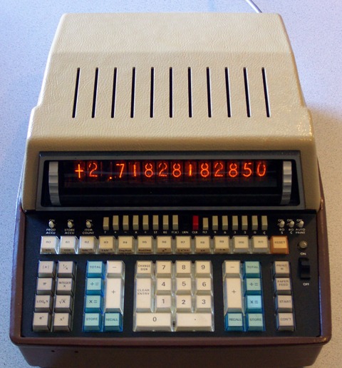
Consolidated Lankville Calculator Model R285
“Every year, we’re going to see the calculating machine get smaller,” noted Jarrad Heaths, an engineer with Consolidated Lankville, one of the nation’s biggest manufacturers of calculator electronics. “Eventually, I think, they will become small enough that one will be able to stick them into one’s pocket,” added Heaths, who pointed at his breast pocket for illustrative purposes. “You’ll maybe be able to get a little case for them and you can put them in your pocket, maybe fill all your pockets with calculating machines, walk around like that. That is really our aim here at Consolidated Electronics.”
Trade magazines consider the Consolidated Model R285 to be the best desk calculator on the market. “It has a lot of functions and it comes with a thick canvas tarp,” said Heaths, who allowed us to briefly paw at the gigantic machine. “You’ll note instantly that you can type 12 numbers on the digital display face. There are also these little vents on the top of the machine which allow for cooling. The R285 does put off a lot of heat and, in extreme cases, fire which is something we’re working on,” admitted Heaths. “We advise in tiny print at the back of the 382-page manual that you only use the R285 for 15 minutes at a time, allowing then for 30 minute “cool-off” periods. Still, this is better than our competitors.”
Briss, Inc. is one such competitor. Briss Calculators began producing calculators just three years ago. “I got hooked and I when I get hooked, I go all out. That’s why my last name is Calculators. I had it legally changed. It used to be “Hubbard,” said the executive, who was interviewed in a windowless, brown-paneled office built into the side of a rural hill. “The R285 is all well and good but it’s got no elan, no pizzazz. I mean, a guy that buys an R285– he doesn’t get excited about it like you’d get excited by a sports car or tits. He just says, “Well, guess we need one of these,” and he doesn’t even bother to look at it. Just takes it out of the box and dumps it on a desk. Briss aims to change all that.”

Pastoral setting where a BI002 was located.
Indeed, a Briss is all about design. Their catalogue currently features six models, all of them impossible to ignore. “They are very conceptual,” noted objet d’art critic Fritz Mallarme. “We are already seeing them featured in exhibits,” added Mallarme, who was wearing a balloon tie. “Even the way in which they are packaged is intriguing. The BI002, for example, is purchased at an ordinary electronics store. However, the buyer must “find” the machine, which is often located in a pastoral setting. It’s quite outre.”
Technically, however, the Briss has not been popular in the trade magazines. “Well they put them in fields,” said electronics expert Dan Awnings, an occasional contributor to The Electronics Cranny. “The rain, the dew ruins them. You end up with a digital face that is only partly readable.” Awnings took a moment to look around in disgust. “Also, they catch fire pretty easily too. The desk calculator has a long way to go still.”
Look for further updates in future columns of The Electronics Cranny.
The Electronics Cranny: So You Want to Be a Ham
By Fritz Tennis Electronics Expert
Long ago, the only requirement for obtaining the lowest level amateur radio operator license (Ham Class) was being able to pass a five words-per-minute Morses Code Test. Still, many people failed even this. In fact, the code test kept many an aspiring Ham from ever even taking the test. Many died, lonely and fat, in dark, spare, curtain-less rooms, unable to even bring themselves to look out at the world which fully recognized their abject failure. It was a sad period.
But as time has marched on, it has become significantly easier. “It’s a reasonably simple test now,” noted Lankville Communications Commission (LCC) associate Lance Heath. “We dropped the code requirement and instituted the 35-question true/false written test. We also don’t really monitor the test very closely so there’s an awful lot of cheating. Probably something we should look into.” Heath yawned expansively and began staring mindlessly at a series of binders that lined his window ledge.
By means of helping the hopeful ham acquire his license (and also become familiar with some of the basic questions of operation), I will outline some of the most frequently asked questions below.
Q. What is the best way to measure frequency drift on a transceiver?
A. The best way is with a small, low-cost frequency counter. Be sure not to limit to one band and be sure to extend your arms outwards far in front of you and from a high window if possible. Wave the counter up and down and then move it in circles. Make sure it’s daytime and some people are around, watching you as you hang out of the window with your counter– this will significantly help your readings.
Q. How can I get a more uniform response from a pair of magnetic headphones having a dc resistance of around 4000?
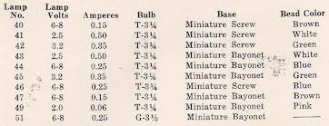
Figure One
A. Common problem. Refer to figure one. You’ll notice that Lamp No. 40 requires a miniature screw compared to a bayonet. This is what we see happening time and again and there seems to be no end to it.
Q. How do you know if your cables are any good?
A. The best way is to buy a large, specialized device available by mail from the Electronics Cranny. It reads in the thousands of megaohms and will be able to tell immediately if you are working with faulty cables. If you want to be cut-rate about it, then use a scope. If a scope is not available or if someone crushed yours in a challenge, then a VTVM set at the highest range might work.
Q. What is a good study guide for the Ham license?
A. Ham License Guide Today is a very good reference marred only by the strange inclusion of a series of lewd photographs of the author. Fritz Tennis’ You Too Can Be a Ham Right Now, Everybody! is probably the most up-to-date publication on the subject as the author edits it continually late at night while his sexless wife snores loudly in the next room. Other manuals or guides may not be revised sufficiently to include the latest changes in the LLC exams.
Q. Once I get my license, will I be allowed to broadcast my own version of the news?
A. Absolutely not. The LCC strictly forbids you from communicating with anyone other than fellow hams. Broadcasting news, playing music, or cussing of any kind will cost you all of your ham equipment and likely a fine and some time in jail. “Yeah, we have a little van to go after those guys,” noted Heath, who had fallen asleep while staring at the binders. “Do that and it’s possible that we could show up at your door.”
Hopefully, this will help you on your way. Good luck!
The Electronics Cranny: Lankville Radio Programming for Tomorrow Morning

By Neil Cuppy
Tomorrow morning’s radio programming has been announced for Lankville’s seven major stations, according to Communications Overseer Harry Rowley III in a report issued today. Transmission will be limited to the amplitude modulation (small) waves operating under the call names LTAB, LFRC, LFWI, LQRC, LWWY, LOTT and LPIP. “Anyone with any questions is free to write us from time to time,” stated Rowley, who was interviewed while inspecting some farm equipment. “We have a little mailbox and we can accept most things from postal carriers.” “When will the afternoon and evening programming be announced?” we asked. There was a long pause, silent as the grave followed by Rowley shaking his head slowly and spitting menacingly in the dirt. “We’ll let it go on an’ happen that way, then,” was the last thing we heard Rowley say before he moved slowly towards us.
The schedule below is taken directly from Rowley’s original dispatch.
6-7:00 A.M.
LTAB: Health Exercises and Entertainments
LQRC: Restrained Cheer Hour
7-8:00 A.M.
LTAB: Health Exercises and Entertainments
LFRC: Morning Encouragement
LFWI: Seals: What Are They?
LQRC: Early Bird Hour
8-9:00 A.M.
LTAB: Health Exercises and Entertainments
LFRC: Health Exercises
LFWI: Musical Breakfast
LQRC: Down Memory Lane with Oleg
LWWY: Home Life
LOTT: Health Exercises
LPIP: Popular Selections
9-10:00 A.M.
LTAB: Health Exercises Until 9:30 Followed by Dead Air
LFRC: Small Business Parade with Shelley Reports
LFWI: Restful Hour Sponsored by the El Arroyo Bank of Del Lankville
LQRC: Highlights, Weather, Deaths
LWWY: Regg’s Daily Chat (with William A. Hancock at the Piano)
LOTT: Health Exercises (with Breathing)
LPIP: Children’s Hour
10-11:00 A.M.
LTAB: Health Exercises
LFRC: Your Decorative Ham (with Chris Vitiello)
LFWI: Scripture, Instrumental Selections
LQRC: Dean T. Pibbs Takes Your Questions/Country Store
LWWY: No live broadcast. Distant string music will be played
LOTT: Johnny Ludlow, friend to boys
LPIP: Crop Report Sponsored by Chambers Company Hand Drills
11-12:00 P.M.
LTAB: Health Exercises, short break
LFRC: Farm Report/Time Signals from the Naval Observatory
LFWI: Concert Orchestra of the Cloud Motel (Hits of Today)
LQRC: Live coverage of the Lankville Commonwealth Luncheon from the Palace Auditorium
LWWY: Some trumpet sounds
LOTT: The Girl’s Half Hour with Ida Rumpus/Dead Air
LPIP: Birthday Celebration for Bill Connelly, Eastern Lankville
The Electronics Cranny: The Truth About Quartz Crystals

File Photo
By Fritz Tennis
Electronics Expert
The type of micro-precision that you find in everyday clocks, door hinges and basketball hoops is entirely keyed to a tiny slab of quartz crystal held under specific temperatures in an extra-special oven. Although the quartz may soon be made obsolete by an even more precise discovery (the little movements of restrained cesium atoms), the crystal still remains the most important device in existence today.
The quartz crystal was known to the ancients and even during the Reign of Pirrapods but it appears that some time after the death of the great King, it was forgotten. It was not until 1837, when Keith Hernandez wandered into a cave in the Inner Depths and was able to hear strange sounds from above, that the power of the quartz crystal was rediscovered. Keith, of course, is now a Hero of Science!
How They Are Cut. Quartz crystals are cut from so-called baby stones by a high-speed carborundum jenny. Don Jars is one of Lankville’s best jenny operators. “You have to know what you’re doing,” he says, by word of advice. “You can’t just step up to the jenny and start cutting. That never works out. I’ve seen guys just walk up to the jenny holding a gigantic sloppy sandwich and think that they can just go ahead and eat the sandwich and operate the jenny with one hand. And still, I’ve seen other guys just walk up to the jenny with an ear of corn. I mean, how can you operate a jenny when you got no hands free?” We had no answer for Jars and the interview collapsed of its own accord.
Although most finished plates come from natural quartz prisms, modern techniques for growing baby stones in laboratories have been perfected to such a degree that the quartz itself may be said to be perfect. Synthetic crystals are often even far superior to natural ones. Zharenendolf Gonzales (foreign Islander) works in one such lab.

A quartz crystal. That’s a hand holding it.
“I would concur with your assertion,” he noted, whilst monitoring the creation of a new synthetic quartz. “We can also make the synthetic quartz to have a pleasing color. Look– this one is green!”
Everyone was very pleased.
Characteristics. The most important single crystal parameter is what is known as “the temperature+mass+coefficient (see table one). You will immediately notice that the temperature coefficient of a certain crystal is given as 1-2-0-6 or 0-2-9-4; hopefully things are beginning to make sense now and you will begin to have an understanding of the megacycle of basic frequency. If you don’t, I wouldn’t really worry about it– it doesn’t really matter. The important thing is to assume that the temperature of your crystal should not exceed x 10=2250 cps= .00225 mc (about the same temperature as it would be if you cooked a bunch of fries in your oven).
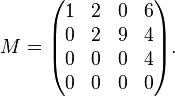
Table One
Have another look at table one, specifically rows 3 and 4. Now look at the equation below:
X-cut: t = k/F = 112/4 = .0028″
Y-cut: t = k/F = 77/4 = .0019″
From this it is evident that the wider crystals will grow thicker. You may wish to make a note in your tablets.
Overtone Crystals. An overtone or harmonic crystal is one that has been ground or otherwise agitated by the manufacturer so that it vibrates in two or more parts rather than as a whole. Essentially, this process is very similar to the production of musical instruments where the body vibrates in parts showing nodes and loops along its length (imagine a tuba). If a crystal were to vibrate in two equal parts, you would get the same effect. Imagine a tuba once more and then look at figure one again.
Mounting. It’s important to have a nice holder for your crystal. The consensus at The Electronics Cranny is to utilize some of the recent plastics; you can also use wood if you live in the hills. The crystal should be allowed to vibrate gently but not excessively– excessive vibration may cause coefficient disintegration and ultimately place the operator in a position where he will have to clear the area. “I’ve seen it happen often with these guys that try to mount crystals while holding a big sloppy sandwich,” said Don Jars. “You can’t have that kind of monkey business!”
Now You’re Done! If you’ve made it this far, you clearly have a working knowledge of the quartz crystal. Now, experiment! Put the crystal in some paper and ball the paper up. Send some signals through a long tube. Try drinking some soda through the tube with the quartz still stuck inside. Enjoy!
This has been another session of “After Class” with Fritz Tennis.
The Electronics Cranny: LASERS!
By Fritz Tennis
Electronics Expert
File Photo
One day last January, two Lankville scientists and Electronics Cranny contributors, stood on a mound outside a swamp. Beside them, mounted on a tripod, was a cylinder no bigger than a flashlight or one of those funny decorative tubes. At a precise moment, one of the scientists pressed a button on some nearby electronic equipment. Instantly, a brilliant red flash shot from one end of the cylinder. And although the two scientists were killed instantly, people standing on a rooftop 250 miles away, were able to see the flash with their nude eyes.
This accomplishment seems unremarkable enough. Indeed, at the time, the two scientists were heavily-criticized as “dolts” or “clods” or “stupid assholes”. Yet Dr. Caramel Jameson of the Solid Electronics Research Foundation thought otherwise. “When I heard of the experiment, I knew right away that a new era of communication had begun,” said Jameson, who we interviewed while purchasing some tennis balls. “I knew that this new kind of light had never been seen before on earth or in Hell and I felt that a device which could tap this power, just alternately love it and tap it, would allow mankind to possess a light beam of unparalleled intensity, even purity. I made a chart about it.”
Dr. Jameson produced the chart which he had carefully laminated. The points were:
- true amplification of light for the first time in history (including Hell)
- the first truly coherent (single-frequency) beams of light ever produced by man
- a so-called atomic clock 1000 times more accurate than our best current models (including those possessed by Hell)
- a super heater that can pour out billions of watts of energy into an area the size of a pinheads [sic]
- a radio transmission system of such tremendous capabilities that it could carry more than 1,oo0,000 simultaneous television signals using only a single channel.

Here’s what the tube looks like.
“I knew that effectively, mankind had created the laser,” Dr. Jameson added.
What the Laser Is. The laser actually stems from another development several years old. As you may have noticed, there’s a similarity between the words “laser” and “vaser,” and the similarity is more than coincidence. A laser is simply a vaser capable of operating at advanced frequencies within our visible light range.
In spite of its tremendous promise, the laser is an extremely common-looking device. It is nothing more than a cylinder of synthetic rubies and field greens about 1/4″ in diameter and 1-1/2″ long, mounted in the center of a spiral coil of binder clips.
To operate the gadget, scientists send a jolt of current through the gassy tube, setting off a brilliant flash of light. Some science is involved– electrons in the rubies and field greens absorb this light and redistribute the energy at another frequency (no graph available). A pure ray is then produced. It is this ray which is capable of performing the feets [sic] mentioned earlier – as well as a number of others – because it is utterly unique in several important ways. Let’s see just what makes the laser’s light so different.

The lasers, as represented by dots and arrows
HOW THE LASER WORKS
Let’s say that, for some reason, you decided to get into a barrel filled with water. As you entered the barrel, some of the water would spill over the sides in a comical manner. Keep this in mind.
Now look at the graph. Note that in “Area B”, the lasers are emitting a longer shaft of light. A shaft of light is being reflected back into the universe simultaneously. That shaft of reflected green light is interacting with the hundreds of stars in space to create a sort of “table tennis” effect.
A chain reaction builds rapidly. Because the ends of our rod are arched and silvered, the emitted light bounces back and forth, stimulating still more atoms to give up their energy. Our rod will soon penetrate these atoms, rocking them slowly back and forth at first but ultimately pretty much bending them over backwards and really having at it. Soon, tremendous quantities of light are rushing back and forth in the rod like water sloshing back and forth in a bathtub (the noise is also similar). Finally, it reaches such a level of intensity that it bursts through one end of the rod (one end has less silver than the other) and shoots forth in a brilliant, coherent ray.
How great an impact is the laser likely to have on the field of communications? Right now, it’s anybody’s guess. But those in the field make no secret about the fact that they are tremendously enthusiastic about this new gadget. “This rod is exceptional,” noted Dr. Jameson. “It never has a problem with busting wads of light all over the place.” With usable frequencies already badly overcrowded in many regions of the present radio spectrum, any system that promises to open up vast new chunks of deep space is something to get excited about.
Perhaps the potential role of the laser in communications is best illustrated with a remark recently made at a laser convention in Eastern Lankville. Said a participant, “We’re not ready to start replacing telephone lines yet.” But he added with a smile, “we’re beginning to think about it.”
The Electronics Cranny: Model Plane Control…with TUBES!
By Neil Cuppy
Electronics Expert
File Photo
Military use of bombs and little missile planes for targets and test purposes has become a big part of the news these days. But the use of tubes is not merely limited to the Lankville Army and Signal Groups. Like an eldtritch creeping puss, it has spread to the amateurs who can build and fly small gas-engined planes as a type of hobby. The development of miniature (small) components and compact tubes has reduced the size of radio-controlled model planes to half of what it was ten years ago (graph available upon request).
One of the most valuable aids to radio control of model planes is the Yount RK-61 tube. This tube, a gas thyratroid tube with triods, requires so little operating current that it is now possible to reduce the weight of your model plane to only 17 1/2 pounds! The RK-61 was in short supply for awhile (some cadaverous halfwits attacked the plant) but now may be found with ease at your local electronics supplier.
For demonstrative purposes, I’d like to share my design schematic for the “Paulhan-Tatin” Aircraft, popular during the Teets Island Skirmishes of 1932-1934 (see figure one).
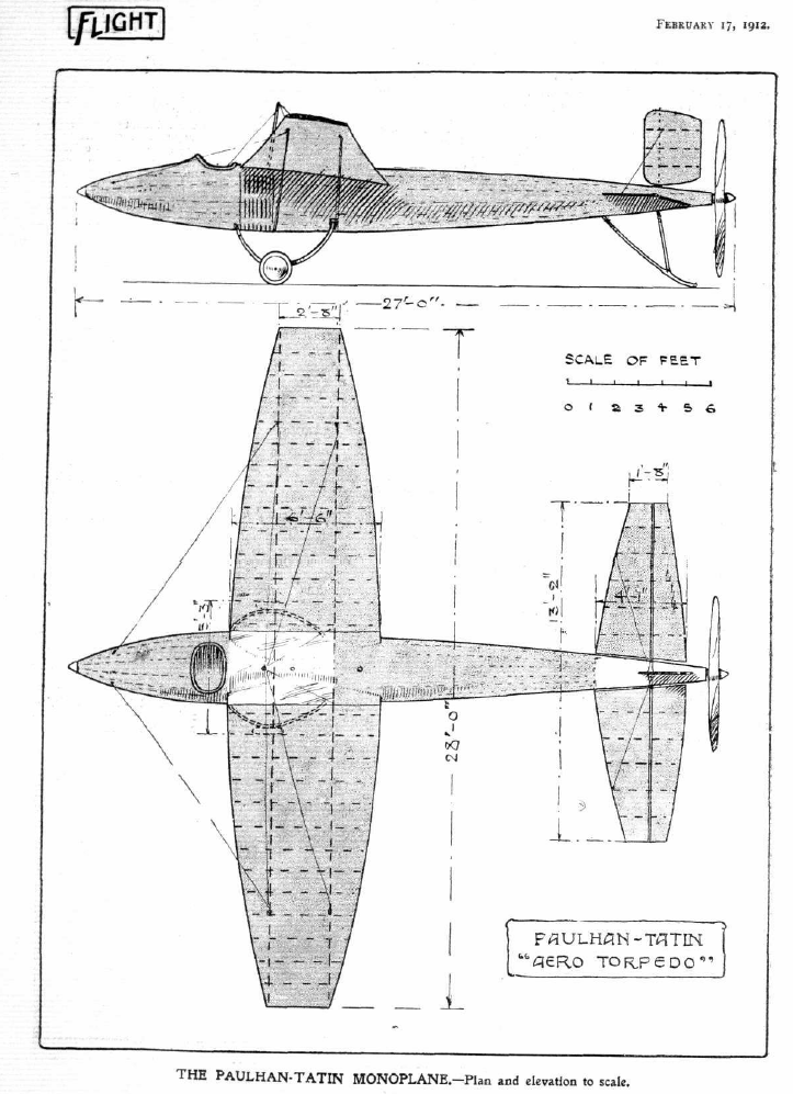 Let’s begin by looking at the parts related to the Escarpment Mechanism.
1. Bulkhead
2. Loops (rubber)
3. Cranks
4. Bowls
5. Carpeting
6. Strappy Paddle
7. Fin
8. Esoteric area of crushing, debilitating depression
9. Large round legs– makes it sturdy.
10. Coils. No. 32 out of the catalog. Wound it round the shaft in the way that the hindquarters of an offering beast might suddenly appear out of the shadows of your room.
11. L-shaped bracket
12-15. For illustrative purposes only
Hopefully, you are beginning to see how the parts fit together to make your plane fly with tubes. Most important is the acquisition of quality loops. This is the one thing that hobbyists often forget. You will be sorry, however, if your plane flies onto a roof or into a tree or is crushed between two large rocks situated together like a couple of grand, folkloric titties. So, do not skimp on the loops.
Next, insert the tubes. The tubes should fit neatly into the area between the carpeting and the strappy paddle but should not touch either component. Insertion should result in an immediate loud humming noise. Don’t worry– you’re not going completely and slowly crazy nor are there mummies in the area. This just means everything is working properly. The tubes will continue to hum in this manner throughout our session.
Finally, throw your plane into the air from a high elevation– I recommend a parking garage or perhaps a tall hill. WARNING: as soon as you throw your plane into the air you will want to immediately engage the remote control– failure to do so will simply cause your plane to plummet to earth. Nobody wants that to happen.
The Electronics Cranny: PIPES!
By J.H. Bangley
President, Electronics Cranny Industries

File Photo
Pencil-size pipes carry telephone messages and TV across Lankville through the System’s coaxial cables. Once, each pipe could carry 6,000 voices, or one TV show. Now, it can carry 58,000 voices or 600 voices plus three quality TV shows. So, you can see that progress has been made.
Yet the pipes aren’t any larger. They are being made into triple-duty voice tubes by new repeaters, new terminal tube equipment, tents and other transmission sheet advances developed right here at Electronics Cranny laboratories in Southern Lankville.
Our conversion expense is less than the cost of laying extra coaxial cables and also less than the cost of, say, fifty pink clothes hampers. But it calls for highly-responsible manufacturing procedures which are made possible only by the close co-operation of The Electronics Cranny and some factories in the mountains.
In improving the coaxial cable systems that were created more than 85 years ago, engineers at The Electronics Cranny have devised a new way to give Lankville better TV service, better telephone service and improved access to pipes while keeping costs low.
Sincerely,
J.H. Bangley
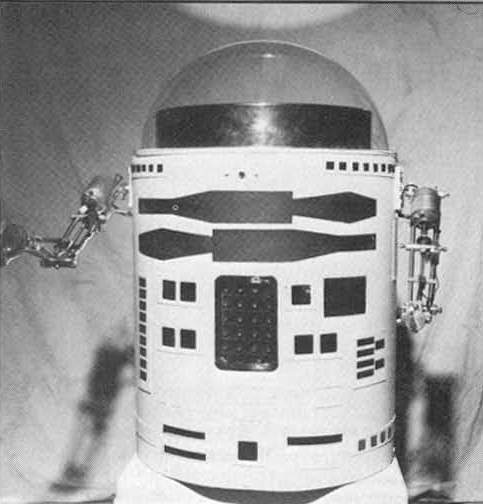
Build This Semcon-1 Robot
By Wayne Lemons
Pondicherry Association News Electronics Expert
Robots are becoming very hot items these days. They already have made a name for themselves in movies, on TV shows and in basketball games. This past January, a week-long conference and an exposition on Robots was held in Lankville City and a second conference (with hopefully fewer murders) will be held during the summer.
This article vaguely details the construction of a robot called Semcon-1 (Semcon standing for “Semi-Controllable”). And although we may not be able to tell you how to build a device as elegant as famed Richard and the Postman TV robot “Cobbs”, we will explain step-by-step how to design a fully pushable robot with funny manipulator arms that will be able to grasp, tilt and carry. These features, in combination, will enable your Semcon-1 to perform an incredible array of useful functions.
Since we are building a robot from scratch, it might be a good idea to become familiar with some of the components which may affect its operation.
There are two electro-mechanical parts which are used to animate your robot– motors and condenser pots. Motors are used to impart continual motion and also will lift the funny arms. Condenser pots are used for the full-arc spasm element of your robot and will be accompanied by gears in mathematical terms. Quality and non-quality condenser pots will be available at any respectable electronics shop– there are a lot at the malls, for example.

Figure One
Now, let’s begin with the manipulator construction (see figure one). Before we proceed, read and pay a lot of heed to the following precautions about working with robots:
-Always wear goggles or some sort of protective eyewear. You can wear a mask with eyeholes cut out if nothing else is available.
-Never wear a tie while working. It can get caught in the robots funny arms and cause serious injury.
-Hold tools properly and towards the body or while filing metals.
Now we can move forward to the question of the two different diameter steel rods. The cross members should be cut from 0.375-in. (3/4-in.) to somewhere in the neighborhood of 20 threads-per-moment. The shoulder and elbow hinges and the two contractor-bar pivots should be cut from aluminum plate. Review.
That accomplished, you should be about ready to put the head on. Take note of the Eprom Bulb which is, again, available at most mall accessory stores. Important not to skimp here and I would strongly urge you to go with the Linear Lamp 10 over any of the cheaper options.
And finally, you can put the funny arms on. While this may sound complex at first reading, it can be done and will yield a perfectly workable and funny robot arm. You are encouraged to use some surplus sheets to keep costs down. For convenience sake, however, a list of components and their sources is shown in the heavy parts list, available as an ancillary article in the “Special Projects” notebook.
Should you have a question about any part of this series, the author may be reached in care of The Pondicherry Association News who will forward your request on to my current location in the Lankville Protectorate.
ACCOMMODATIONS

When staying in the Area Beyond the Outlands, pick the Murray. Friendly, creative staff, delightful beds, curtains. Phone Far Outlands 5-6712.
LANKVILLE DAILY NEWS: IN BOOK FORM!

The book is gone. It will never return. We hear stories but they are likely false. We live in the woods now. We make fire with a lighter that we found in the street. It was crushed by a truck but, somehow, perhaps through some intervention that is beyond us, it still works. We are waiting. We are waiting.

Original Pondicherry Association News promotional advertisement (2009)
TONIGHT ON TV! RICHARD AND THE POSTMAN REUNION SPECIAL!

The Hit program from the 1970's returns to Lankville TV tonight on LBC!
ADULT ADVERTISEMENT

Women all over Lankville are just sitting at mammoth computers waiting to hear from men like you! Just insert a floppy disk, write a (non-sexual) message and let the sparks fly! (Computer not included).
ADVERTISEMENT

A Vitiello Decorative Ham makes a great gift. Show that you care today.
BANDED DUFFELS ON PALLETS

Assorted colors. Whatever you want to do, man. Call Lankville Falls, 3247.
BRIAN SCHROPP IN THE LANKVILLE DAILY NEWS

The most important cuisine articles ever written.
CANDY

Jipps Co. Full Service Candy Counter! Our alert girls will push gummy drops into special paper sheaths, engage in restrained pleasantries and explain chocholate-to-nougat ratios. Call Central Lankville 3614.
CAT PHOTO

In compliance with Lankville subsection 11:16-4.
CHAMBERS CO. HAND DRILLS: When Electricity is Not an Option

When electricity is not an option consider the Chambers Company hand crank drills. Perfect for use in tight spaces, on distant islands or for drilling holes in fences to see TITS. Call 4-2309.
EMPLOYMENT

Big Ed's BBQ Shack is looking for a part-time waitress. Someone who doesn't nose around and ask a lot of difficult questions. Call Lankville Rougher Area, 5-2100.
EMPLOYMENT

Nuts, Ah! is looking for an experienced nut-handler. Experience with bagging nuts also important. If you break the nut sack, the nuts will drop onto the floor. Come in person for application to Twin Removed Pines Mall. NO CALLS.
FOX FOR PARTIES

Hire the Poetry Fox for Your Child's Next Party. Reasonable rates. Writes poems, dances, will not stand for any shenanigans. Call South Lankville 2009.

The funny stories of Dick Oakes, Jr. have thrilled millions. Look for them today in The Lankville Daily News!
GELSINGER’S ALLURE CLUB

Topless, bottomless wonderland. Mysterious back rooms. Carpeted entirely in astroturf. NO CALLS.
GREBOV BROTHERS TELESCOPE COMPANY

The Grebov Brothers are Lankville's finest purveyor of telescopes for astronomy enthusiasts. Substantial 4.5" apertures and fast f/4 focal ratios provide bright, detailed views of solar system targets like the Moon and planets, as well as wide-field celestial objects like nebulas and star clusters but also TITS.
GUMP PENETRATES

Only in The Lankville Daily News
HADBAWNIK HAUNTED STAIRCASE COMPANY

The Hadbawnik Company is Lankville's #1 installer of haunted, brush-littered staircases. Friendly non-foreign staff! Call Western (Outer) Lankville, 2154 or 2198 today.
HADBAWNIK HAUNTED BRUSH PILES!

The Hadbawnik Haunted Staircase Company is now offering haunted brush piles for use on your staircase. Create eerie, supernal ambiance. Allow the brush to blow haphazardly in the wind, creates fear, foreboding. Call our friendly staff of white people at Western Lankville, 2154. Brush piles may contain other forms of yard debris.
HEY! WANT A MONKEY?

Hey! Want a live little monkey? They do cute things like climb into pumpkins. Call "The Captain"- Central Lankville Hills, 5264.
HOME DUMP Your Neighborhood Hardware Store 16 Lankville Locations!

Weekly Special: Primitive Forged Hooks. Buy 4, Get a Can of Paint. Or Maybe Not. You'll Just Have to Find Out.
INFLAMED BY STARS AND BLOOD

Lankville's Premier Science Fiction and Horror Magazine Now Appearing in The Lankville Daily News!
JOHNNY PADRES, OPTICIAN

Lankville has been relying on Dr. Johnny Padres for their optical needs since 1973. We offer a full service family eye care center and provide examinations for glasses and contacts and have a large display of designer, traditional and innovative eyewear for both regular prescription eyeglasses and sunglasses all of which will enable you to see TITS better. Call Lankville Business 2618-2.
LIFE LESSONS FUNERAL HOME

Life Lessons Funeral Home has been helping Lankville with dead people since 1932. Contact Eddie or Stummins, Lankville Business, 5-2161.
LOOK AT THESE BEAUTIES!

Really some of our best ever! Have you ever seen anything like it? Call Kelly (male) at Lankville Sound 2615.
MISSING

Missing: adult penguin. Christ, I just let him out in the yard for one minute and now he's gone. Responds to the name "Richard". Call Lankville Eastern Outlands, 5-6213.
NOW PLAYING!

The Unhinged: A New Film by Tom "Vapor" Rayford. Crisp Street Cinema, Eastern Lankville
PINEAPPLE CITY: A New Way of Being

Pineapple City is a new way of being, feeling and having your shirt off. Located in the distant, barren Lankville Pines, Pineapple City is now accepting applications for sheds. Call PINES, 2-5771.
THE PUZZLER

In the pie chart above, what segment represents a certain specific strata of the general population?
REAL ESTATE

Little shed for sale. With door, mailbox, dirt plot. Site of multiple murders but don't worry, they happened around back. To inquire, come to the shed. Go around back.
REAL ESTATE
Four acre lot in Eastern Lankville Cove Area. Price reduced! Site of a fireworks display in which several people fell out of their lawnchairs and died. Locals believe it haunted but that's crap. Call Cove 2751.
THE RECKONER EXACTRA 2.0 : A Danny Madison Product

It's Your Time: CALCULATE
SARAH SAMWAYS: CONTRIBUTING FEMALE

Exclusively in the Lankville Daily News (and some other papers).
SPEAKING ENGAGEMENT

Robin Brox will sit around and get progressively more intoxicated while listening to this other broad natter on about something. LANKVILLE REGIONAL AUDITORIUM, August 4, 11PM.
SPEAKING ENGAGEMENT CANCELED

The Dr. M. Chambers speech and candy-making event has been canceled again following Dr. Chambers' sudden collapse into some baskets. New date TBA
TRAVEL TIPS by Randy Hammers
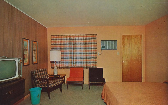
The Kum Back Inn in the Lankville Desert Area has long been serving road-weary travelers. They feature a restaurant (with cocktails) and two spacious conference rooms. The Kum Back boasts 65 units-- each including window dressing, some chairs and a larger chair (seats two smallish children), a bed with orange comforter, a plastic trash can, clever paintings, and a windowless door. TV also available in 17 (sometimes 19) rooms. Most of the rooms are air-conditioned. Oscillating fans available upon request. Illuminated carports will protect your vehicle from the vicious sudden dust storms that often overtake the Desert Area and the wild thieves that occasionally parade across the landscape like some unmentionable horror. Call now at TU-0780 and ask for Bud or Karen (married).
UTILITY YARD SHEDS

The Lowinger Brothers offer great utility yard sheds at low prices. This one is haunted. Call Lankville Port Area 1072.
VACATION PACKAGES!

Spectacular vacations in campers by little mountains. Your cares will melt away but you will have to be careful of that shack (pictured). A lunatic lives there. Call Mercantile District 2711.
WRESTLING TONIGHT!

8PM, Southern Lankville Man-Arena. Featuring Ric "Wild Boy" Tipps (green trunks).
ZACH KEEBAUGH INVESTIGATIONS

Only in The Lankville Daily News

LETTER SACK